
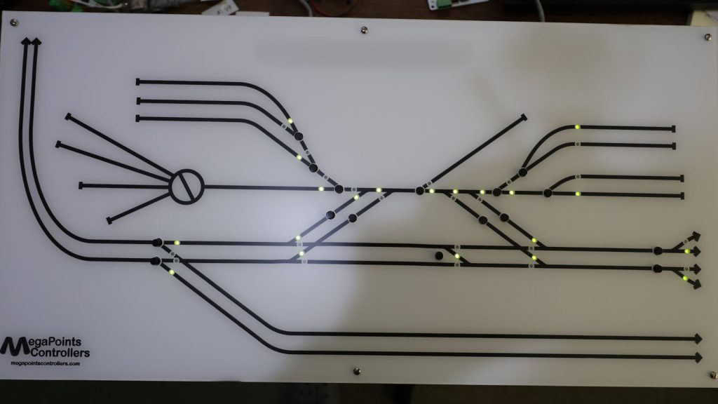
A customer sent us the track plan of his Gauge One garden railway and asked for a mimic panel to go with it. We filmed the whole job, from his track plan to the first light on the finished panel, so here is the story in pictures, and the film if you have 37 minutes to spare.
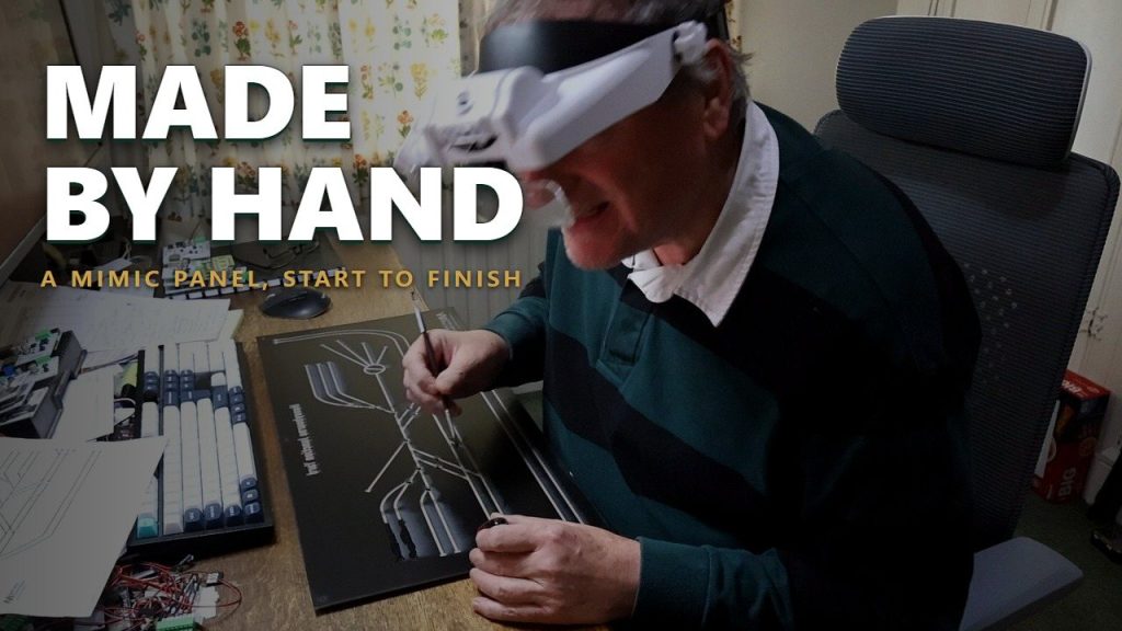
The railway is big: more than 200 feet from end to end. This panel is the first of four, so there are three more to make.
It starts with a file
The customer drew his railway in AnyRail, a track planning program: a long oval with two turntables, a fiddle yard and sidings everywhere. We took one part of it, for panel one, and turned it into a design in PanelWorks™.
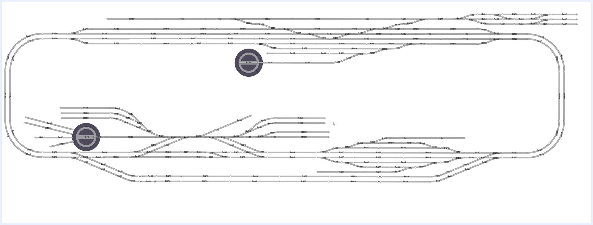
Size matters with a mimic panel, because the face has to be cut on a laser. Our first try came out more than a metre across, which is too big for ours, so we squeezed it down. The finished design is 600 × 300 mm, and it looks all the better for being compact.
One thing to know: the PanelWorks™ designer takes panels up to 500 × 400 mm. This one is wider than that, so we drew it from the workshop’s side of the designer, where that limit does not apply.
Drawing the panel
Then it was a bit of this and a bit of that. We straightened the track, put a button on each set of points and an LED for each way it can be set, and spaced them out so every one is easy to reach and easy to read. The panel ended up with 16 buttons and 41 LEDs.
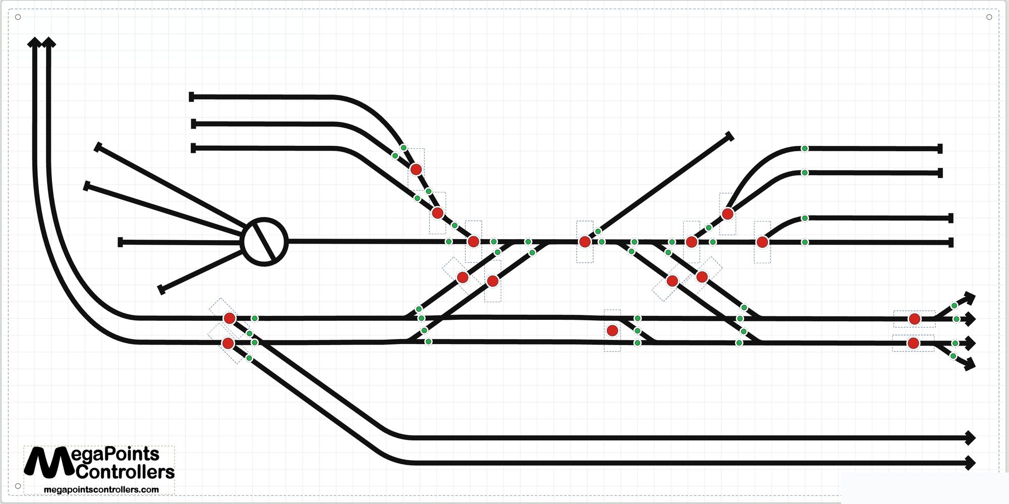
PanelWorks™ checks as you draw. At one point it told us there was no room behind a button for the board that fits there, and that an LED was in the way. A little shuffling put both right.
A sloping box to go with it
We chose a sloping enclosure, and PanelWorks™ drew the box around the panel: 4 mm birch-faced plywood, sloping at 12 degrees, 65 mm high at the front and about 126 mm at the back. A panel 600 mm wide wants more fixing holes than the four it started with, so we added some. We also added a round hole at the back for a network socket, and kept the pair of keyhole hangers, so it can hang on a wall.
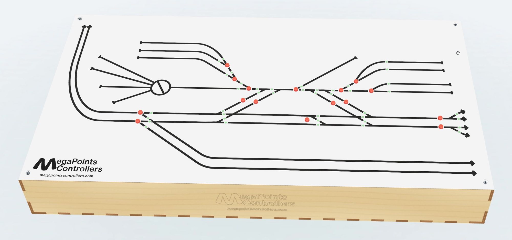
Approved before anything is cut
When the design was ready we pressed Share 3D view and sent the customer a link, so he could turn the panel and its box round on his own screen. He approved the changes, and only then did we prepare it for the laser. Nothing is made until you have approved it.
The cutting files then come straight out of PanelWorks™: one for the enclosure, one for the MDF backing and one for the engraved face. Turning an approved diagram into a drawing the laser can use used to take half a day by hand, and a slip meant starting again on a new sheet. Now the files come out right first time.
At the laser
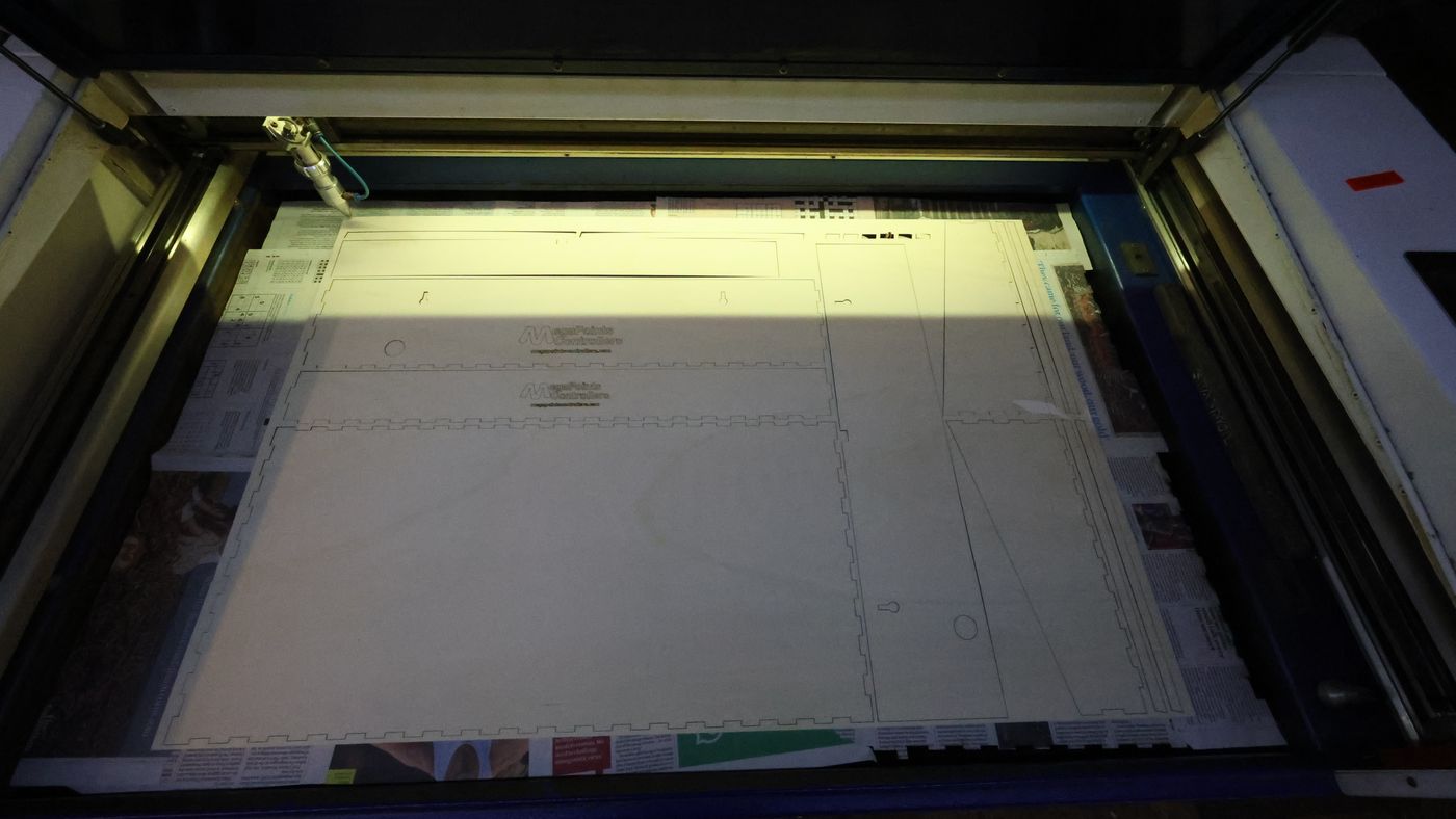 On the laser bedThe parts of the enclosure marked out on one sheet of plywood.
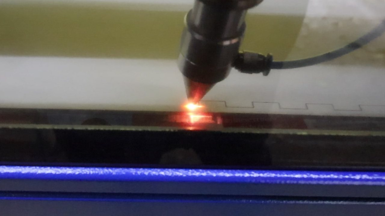 Cutting the finger jointsThe laser head at work, with a bright spark at the cut.
The laser cut all three: the MDF backing that carries the buttons, LEDs and boards, the engraved face, and the finger-jointed enclosure. The plywood we buy is never quite the thickness on the label, so each sheet is measured before it is cut and PanelWorks™ sets the joints to match. That is why they go together so snugly.
Glued up, then painted
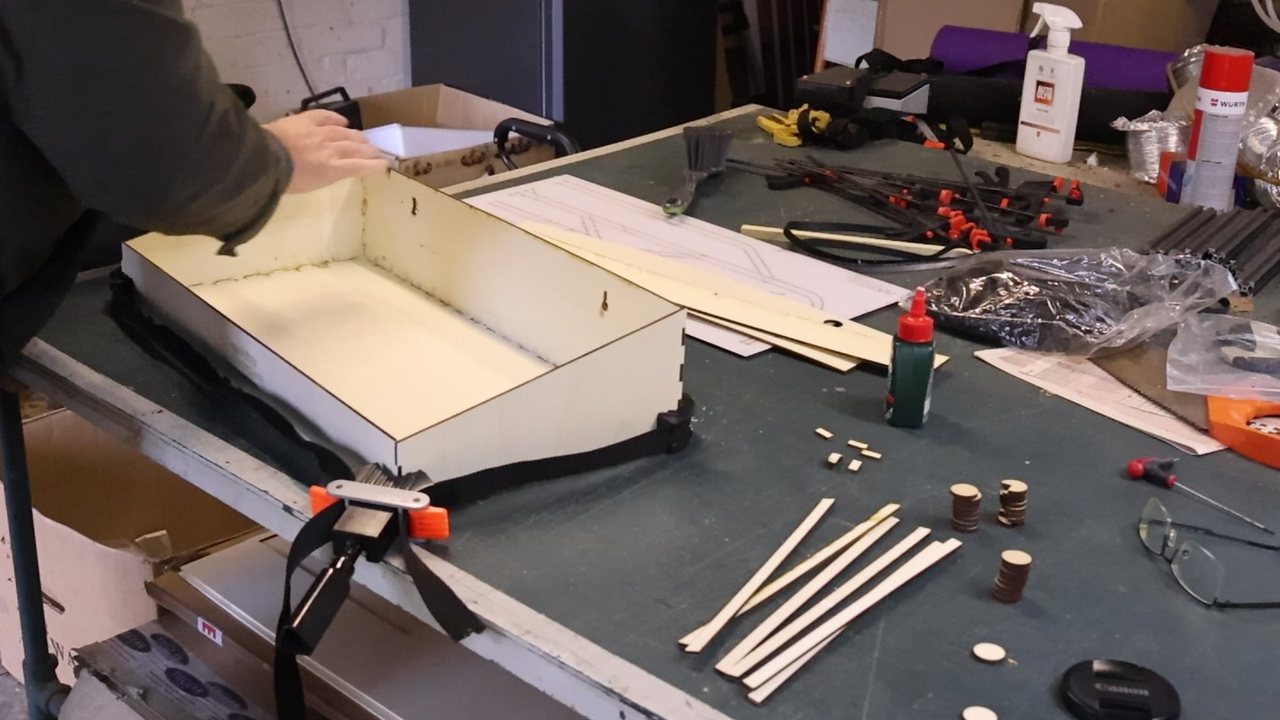 Gluing up the boxWood glue, clamps, and the rails for the backing to sit on.
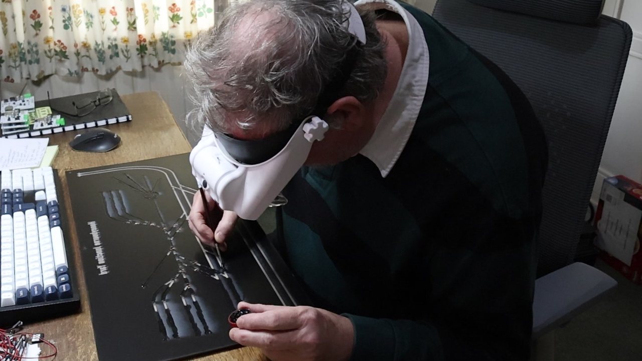 Painting the faceThe black goes on from behind, into the engraving.
The box is glued with ordinary PVA wood glue, because it leaves plenty of time to get every joint home, and clamped until it sets. Inside, rails are built up to carry the MDF backing and take its mounting screws.
The face is engraved from behind and painted black from behind. Black is the easiest colour to apply and it covers very well. We allowed about half an hour for the face.
Buttons, LEDs and the boards behind them
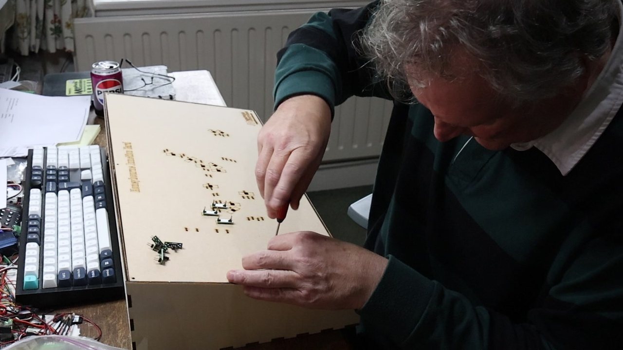 Buttons and LEDs go inThe buttons screw in from behind and the LEDs push in with no glue.
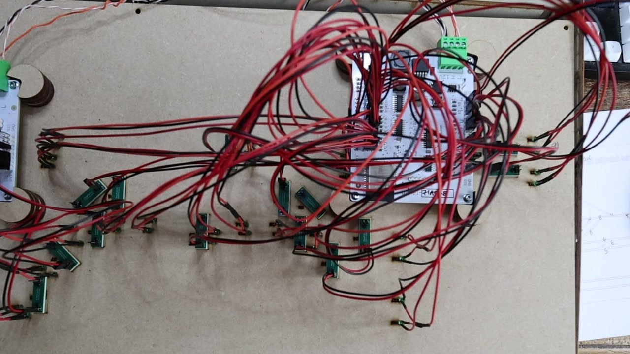 The boards on the backA Panel Controller and a Mini Panel Controller, each lead wired to its socket.
The buttons come in strips of eight and snap apart. Each takes a cap (the customer chose black, though the drawing shows red) and drops into its hole, which is cut so exactly that there is no wiggle room: where it lands is where it is screwed in. The LEDs simply push in, with no glue.
A System2 Panel Controller and a Mini Panel Controller are fixed to the back of the MDF backing, so when the lid comes off everything comes with it as one piece. The only lead going out is one network cable, which brings the power as well as the System2 network. We wrote down which socket every button and LED went into, so setting the boards up afterwards is the easy part.
First light
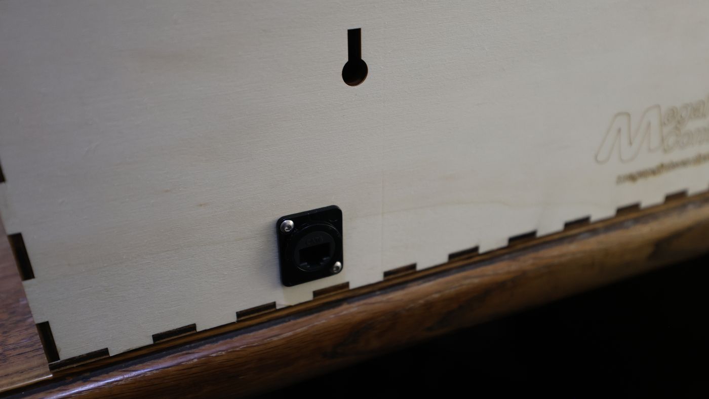 Round the backKeyhole hangers for the wall, and the socket for the network cable.
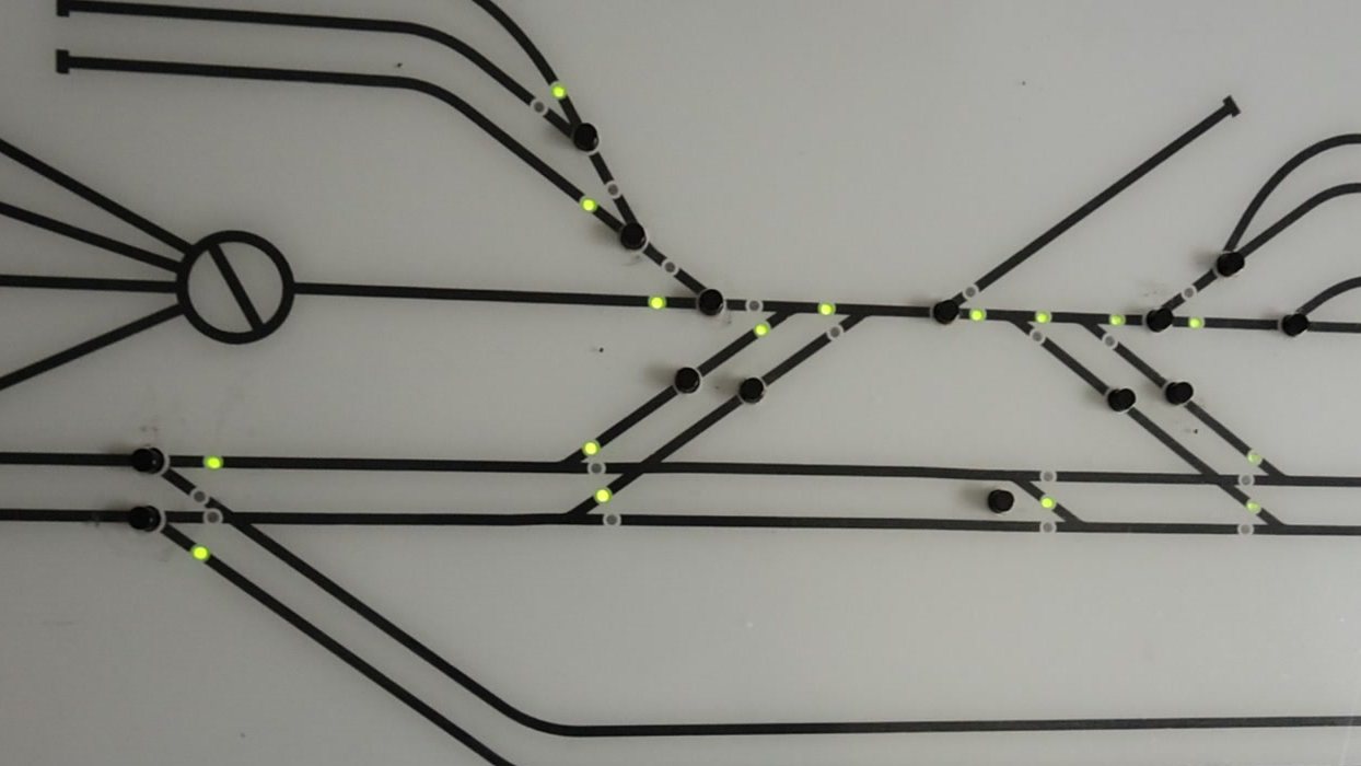 First lightThe LEDs lit beside the black buttons.
Plug that cable into the socket on the back and the panel lights up and starts talking to the System2 network on our bench. It is built but not programmed yet, so pressing a button does nothing for now. Setting up what each button and LED does comes next.
How close is it?
The question we most wanted answered was how close the proof is to the real thing. Here they are side by side: the 3D proof from PanelWorks™ on 22 October, and the finished panel on 27 October.
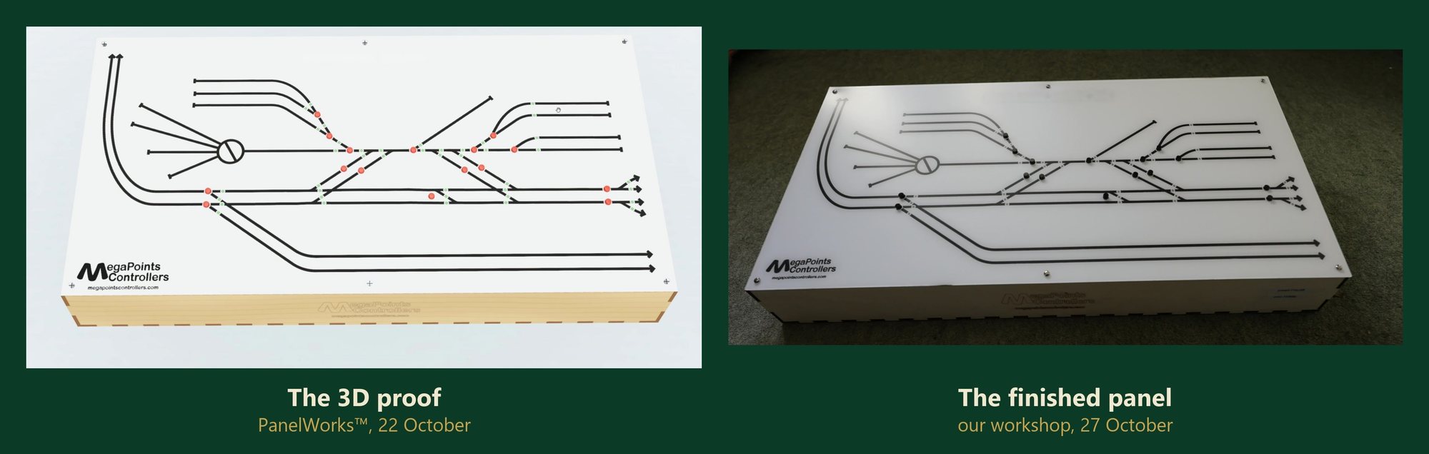
Other than the colour of the buttons, it is a good likeness. In the film we go a step further and lay the design exactly over a photograph of the finished face, and every line, button and LED lands where it was drawn. What impressed us most was how smooth and tight the finger joints came out.
Make one of your own
PanelWorks™ is open to everyone. Draw your panel in your web browser, and we check it, send you a proof and make it. Designing costs nothing, and you pay only when you order.
As ever, if anything does not make sense, drop us a line. We would much rather you asked.
Dave & Sheila